 Вы можете собрать Ethernet-шлюз, используя любую Arduino.
В продаже существует несколько различных модулей Ethernet. Мы рекомендуем использовать WizNet W5100, который разгружает микроконтроллер Arduino и оставляет больше памяти для кода шлюза.
Подключение
Радиомодуль должен быть подсоединен немного по-другому, чем стандартное подключение для сенсорных узлов, поэтому ниже это будет описано.
Модуль Ethernet 5100 имеет проблемы с обменом по SPI вместе с радио. Чтобы решить эту проблему, мы ставим радио на пару других контактов и используем так называемый soft-spi. Вот почему вы должны подключать радио немного иначе, чем на обычных узлах.
WizNET (W5100) Ethernet модуль
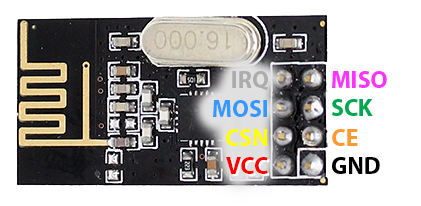
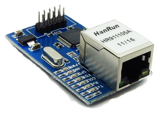
| Arduino | NRF24L01 Radio | Ethernet module |
| GND | GND | GND |
| 3.3V | VCC | VCC |
| 13 | SCK | |
| 12 | MISO/SO | |
| 11 | MOSI/SI | |
| 10 | SS/CS | |
| A2 | MISO | |
| A1 | MOSI | |
| A0 | SCK | |
| 6 | CSN/NSS | |
| 5 | CE |
 ENC28J60 Ethernet модуль
Вам понадобится загрузить и установить библиотеку UIPEthernet, чтобы запустить Ethernet-модуль ENC28J60
В адаптированной версии (мы отключили некоторые функции) для MySensors можно найти здесь: https://github.com/mysensors/MySensorsArduinoExamples/tree/master/libraries/UIPEthernet
| Arduino | NRF24L01 Radio | Ethernet module |
| GND | GND | GND |
| 3.3V | VCC | VCC |
| 13 | SCK | SCK |
| 12 | MISO | MISO/SO |
| 11 | MOSI | MOSI/SI |
| 10 | SS/CS | |
| 6 | CSN | |
| 6 | CE |
Обратите внимание, что модуль ENC28J60 использует намного больше памяти, чем W5100. Вам, вероятно, придется отключить определение MY_DEBUG для его компиляции.
Конфигурация
Выберите статический IP-адрес и порт, которые вы хотите использовать для шлюза.
#define IP_PORT 5003        // The port you want to open
#define MY_IP_ADDRESS 192, 168, 178, 66  // Configure your static ip here
MAC-адрес может быть любым, но должен быть уникальным в вашей сети. Новые платы имеют MAC-адрес, напечатанный на нижней стороне печатной платы, которую вы можете (опционально) использовать. Обратите внимание, что в большинстве примеров Ardunio для MAC-адреса используется «DEAD BEEF FEED»
#define MY_MAC_ADDRESS 0xDE, 0xAD, 0xBE, 0xEF, 0xFE, 0xED
Дополнительные сведения о кнопках включения и светодиодах см. В разделе Дополнительные параметры сборки.
